


 13 / 138

12
Diagnostic Manual
ON BOARD DIAGNOSIS (OBD)
3
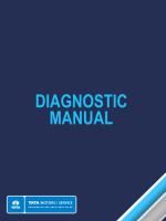
ALL COMPRESSION IGNITION VEHICLES
OBD MONITORING ITEM
MONITORING ITEMS
INDIAN OBD-I
INDIAN OBD-II
VEHICLES ON & FROM VEHICLES ON & FROM
Catalyst
NA
1st April’2013
Fuel Injection System
1st April’2010
1st April’2013
Particulate Trap
NA
1st April’2013
Coolant Temperature
1st April’2010
1st April’2013
Exhaust Gas Recirculation (If Provided)
1st April’2010
1st April’2013
Fuel System
NA
1st April’2013
Emission Control System/Components
1st April’2010
1st April’2013
Circuit Continuity for all emission
1st April’2010
1st April’2013
related Power train components
Distance traveled Since Malfunction
1st April’2010
1st April’2013
Indicator lamp (MIL) ‘ON’
OBD-II Communication Protocols
A communication protocol is a standardized way
of data communication between an Electronic
Control units and a scan tool. For vehicles that
comply with IOBD-II, the following communication
protocols are permitted:
•
ISO 9141-2 (K-LINE)
•
SAE J1850 PWM (Pulse Width Modulation)
•
SAE J1850 VPW (Variable Pulse Width)
•
ISO 14230-4 (Keyword Protocol 2000)
•
ISO 15765-4 (Controller Area Network)
•
SAE J2284 (Controller Area Network)
Since standardized DTC’s and known communi-
cation protocols are used, a generic scan tool with
OBD-II compliance can communicate with the
ECU(s) and retrieve the recorded DTC’s. The
OBD II generic scan tools can be used by the
traffic cops for checking ‘MIL’ related faults in the
engine management system.
Diagnostic Trouble Code (DTC) Breakdown
Diagnostic trouble codes, known as DTCs, are
alphanumeric codes that a vehicle's computer
outputs when it detects a malfunction in wiring
harness, sensors, actuator or any system. These
codes are transmitted by a vehicle's on-board
diagnostics (OBD) system and can be accessed
by using a diagnostic scanner that plugs into
theDLC connector via OBD cable.
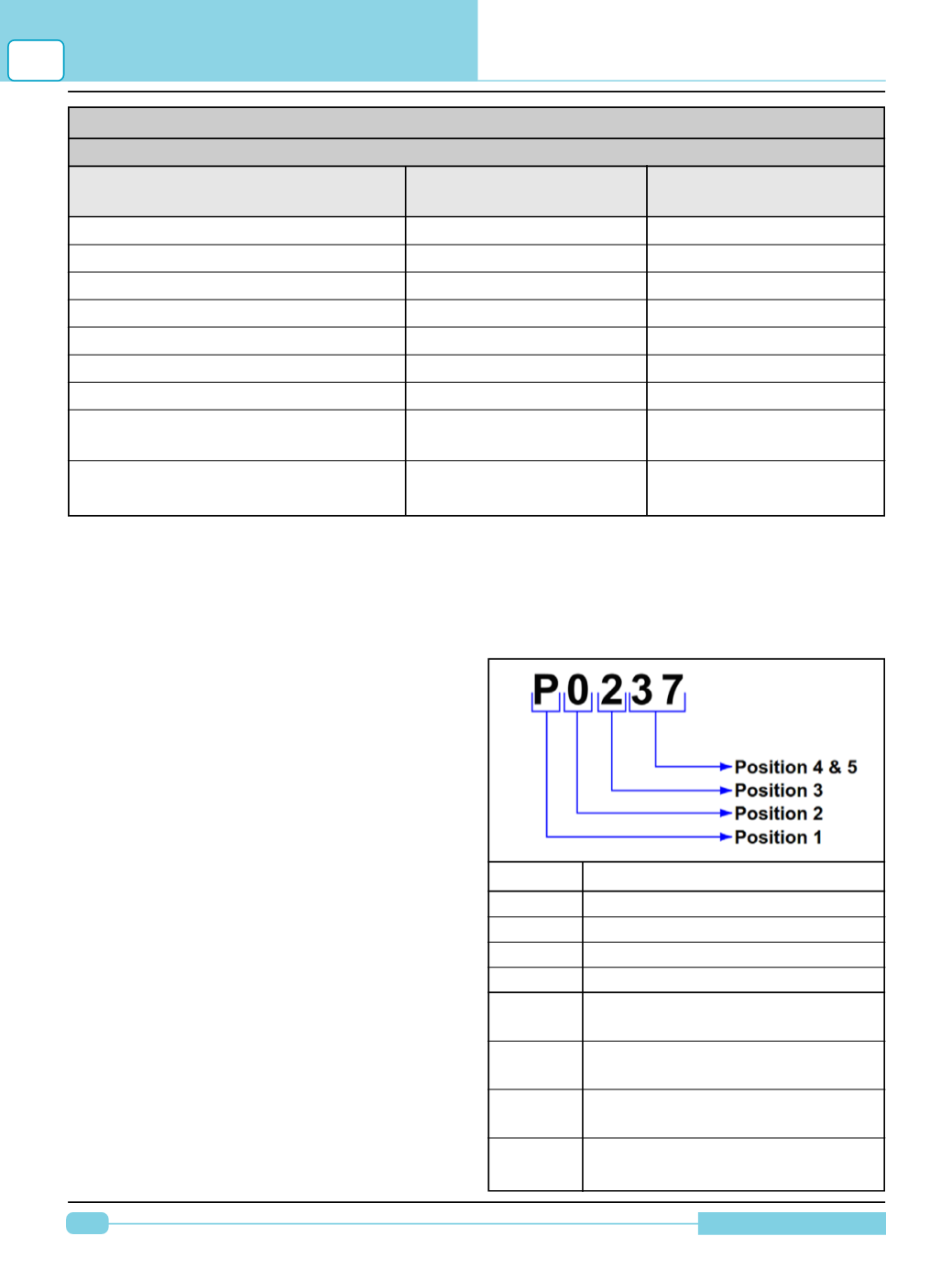
DTC’s are composed of five characters; one
letter followed by 4 digits.
Position Description
1
P= Power train
C= Chassis
B= Body
U= Network
2
0= Standardized emission related
trouble code
1= Manufacturer specific trouble
code
2= Standardized or Manufacturer
Specific trouble code
3= Standardized or Manufacturer
Specific trouble code