


 14 / 138

13
Diagnostic Manual
ON BOARD DIAGNOSIS (OBD)
3
Position Description
3
0= Overall System
1= Secondary air system / mixture
preparation
2= Fuel System
3= Ignition System/Misfires
4=Additional exhaust gas
monitoring
5=Cruise control/Idle speed control
6= Input/Output signals, Control
Units
7= Gear Box/Transmission
8= Transmission
9=Transmission
A= Hybrid propulsion
B=Reserved
4&5 Serial numbering of individual
components or systems
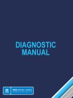
Data Link Connector (DLC)
OBD II regulations require that manufacturers use
a standardized diagnostic connector. This is to
allow a generic scan tool to be used on all OBD II
equipped systems. The newly designed diagnos-
tic connector for OBDII, officially known as theData
Link Connector (DLC), contains 16 terminals.
Data Link Connector (DLC)
DLC Pin Assignments
PIN Description
1 Discretionary
2 J1850 Bus+
3 Discretionary
4 Chassis Ground
5 Signal Ground
6 CAN High (ISO 15765-4)
7 ISO 14230-4 & 9141-2 ‘K’ Line
8 Discretionary
9 Discretionary
10 Bus negative line of SAE J1850
11 Discretionary
12 Discretionary
13 Discretionary
14 CAN Low line of ISO 15765-4 (J-2284)
15 ISO 14230-4 & 9141-2 ‘L’ Line
16 Vehicle Battery Power
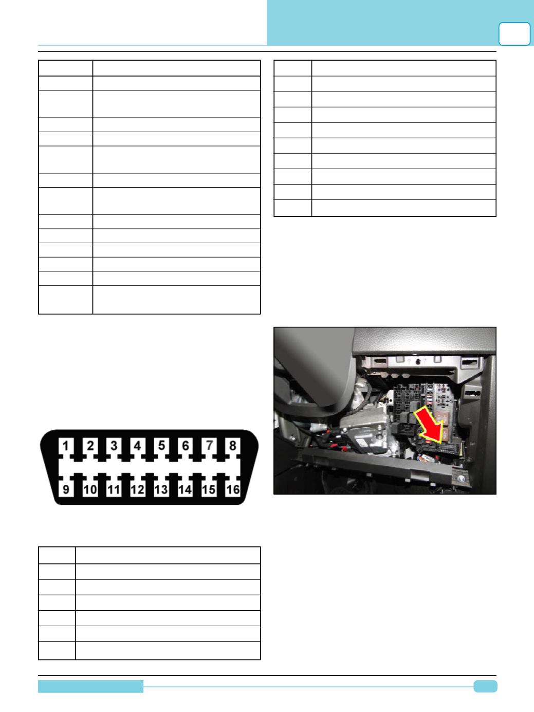
DLC Location
The diagnostic connector is required to be located
between the driver’s end of the instrument panel
and approximately one-foot beyond the vehicle
centerline, on or below the instrument panel. On
most vehicles, the connector is located beneath
the instrument panel, near the steering column.
In
TATAMOTORS
passenger segment vehicles,
DLC location is different from model to model.